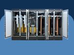
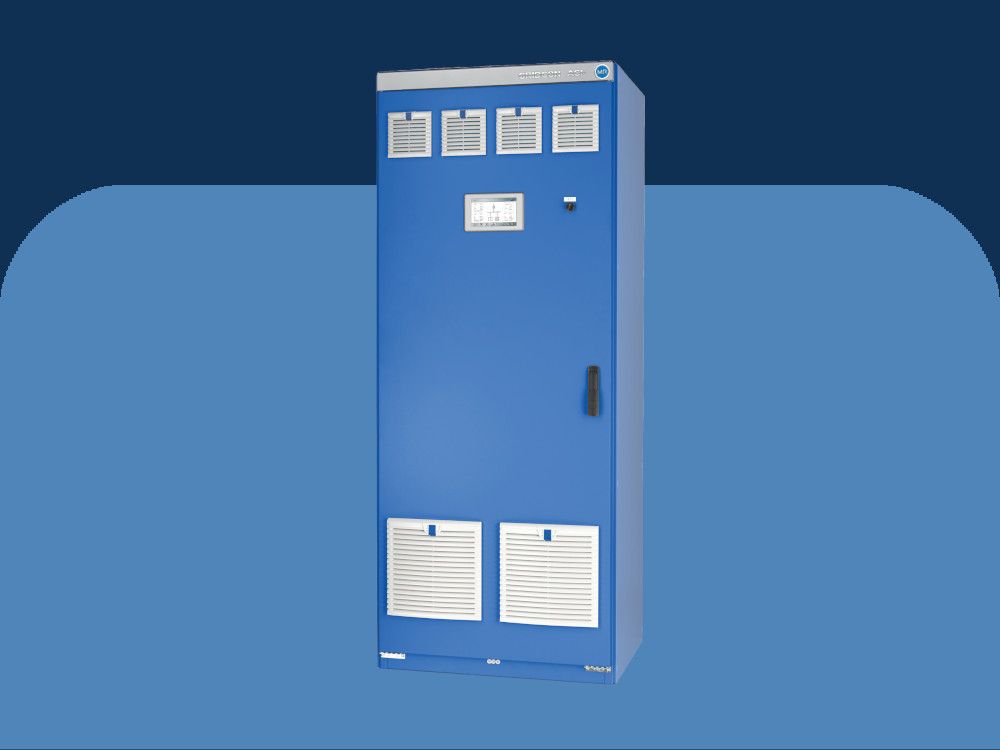
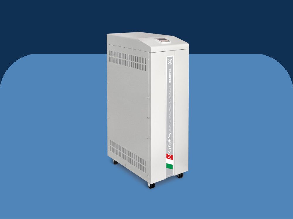
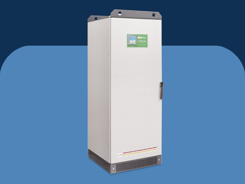
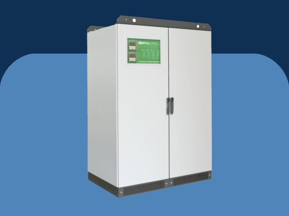
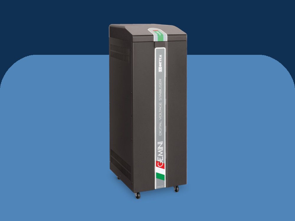
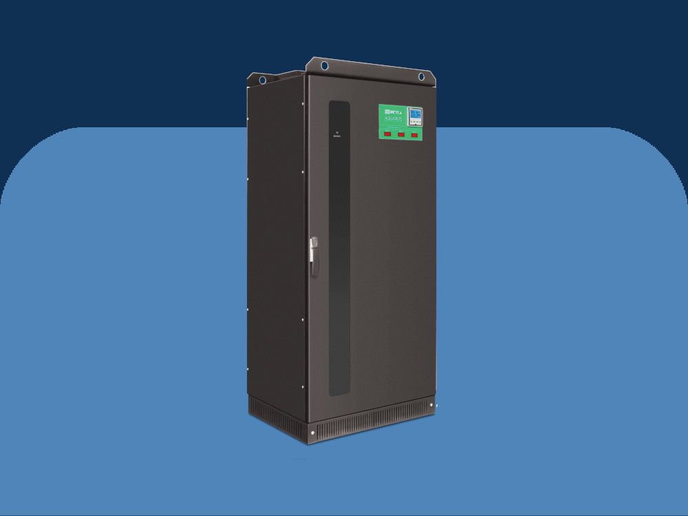
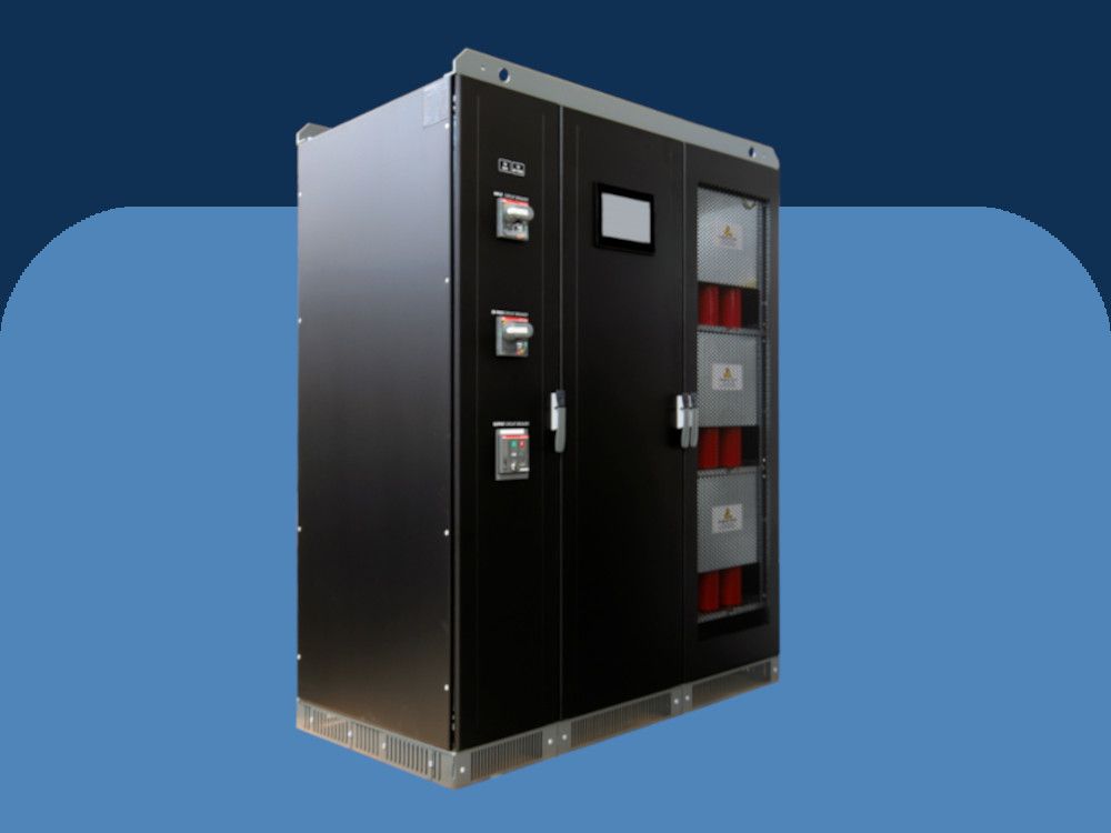
Sirius - 3ph 60-6000kVA electro-mechanical digitally controlled
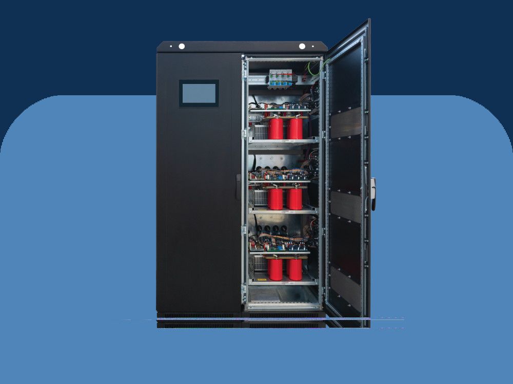
Sirius is a three phase electro-mechanical stabilizer. The electromechanical stabilizers are digitally controlled and are made essentially of buck-boost transformer, voltage regulator and electronic control. By means of the digitally controlled system, the stabilizer is able to compensate for a widely fluctuating incoming voltage stabilizing it within a ±0.5% accuracy range in relation to the rated value. Based on a microprocessor sampling the output voltage at high frequency, the control system operates the voltage regulator motors in order to guarantee the voltage stability. The electromechanical stabilizers are often used in industrial installations, or installations of big nominal power, where the most important criteria are endurance in very high or very low voltages and a high degree of stabilization.
Sirius stabilizers are available for different ranges of input voltage fluctuation. In the ±15%/ ±20% and ±25%/ ±30% types, the change of input range is obtained through different internal connections (only up to 2000kVA ±15% and equivalent). Sirius stabilizers are equipped with columnar voltage regulators which enable the achievement of high ratings (up to 6000kVA) and a solid and reliable construction, thus meeting the most diverse industrial applications.
The Sirius voltage stabilizers regulate the output voltage independently on each phase. Similarly to the other models, they can supply any single-phase, bi-phase and three-phase load even in case of and up to 100% unbalanced load current and asymmetrical mains distribution. In any case, the presence of the neutral wire is required. The stabilizer can also operate without neutral wire by adding a device able to generate it (D/zn or D /yn isolating transformer or neutral point reactor). The stabilizers are cooled via natural air ventilation, assisted by extracting fans when the cabinet internal temperature exceeds 35°C. The user interface consists of a multilingual 10” touch panel (fitted with RS485 port) able to provide with information regarding the status of the lines upstream and downstream the voltage stabilizer (phase and linked voltages, current, power factor, active power, apparent power, reactive power, etc.), the operating status of the stabilizer displaying all the information regarding each phase operating mode (‘power on’; reaching of voltage regulation limits; increase/decrease of voltage regulation, etc.) and the possible alarms (minimum and maximum voltage, maximum current, over temperature, etc.). The alarm indicators are accompanied by an acoustic alarm.
The display is remotable using VNC software. It is also possible to communicate with the stabilizer with the Modbus TCP/IP protocol (standard communication protocol between electronic industrial equipment) via an Ethernet connection with RJ45 cable. The control system is also provided with two USB ports for downloading stored data and uploading new releases of the control card software. The Sirius stabilizer is provided with an electronic voltage regulator protection system activates in case of overload on the voltage regulator. In such condition the load supply is not interrupted, but the stabilizer output voltage is automatically set to the lower between the mains voltage and the pre-set output voltage. The service continuity is guaranteed, although the voltage is not stabilized. When the overload condition ceases to exist, the stabilizer switches automatically back to regular functioning. The control logic is managed by two DSP microprocessors (one performing the control and the other one managing the measurements) which obtain the output voltage stabilization by adjusting its true RMS value. The whole system is supervised by a third ‘bodyguard’ microprocessor that controls the correct functioning of the other microprocessors. The unit parameters and reference output voltage value can be set via a PC connection, allowing for promptly dealing in the field with any issues concerning voltage stability. The output voltage is reset to the minimum value in case of blackout by means of supercapacitor banks in order to ensure the correct shutdown. All Sirius stabilizers are provided with Class I and Class II SPD surge arrestors.
- Voltage stabilization - Independent phase control
- Output voltage selectable via display, PC and/or Ethernet*
- from 210V to 255V (L-N)
- from 360V to 440V (L-L) - Output voltage accuracy: ±0,5%
- Frequency: 50Hz ±5% or 60Hz ±5%
- Admitted load variation: Up to 100%
- Admitted load imbalance: 100%
- Cooling Natural ventilation (from 35◦C aided with fans)
- Ambient temperature: -25/+45◦C
- Storage temperature: -25/+60◦C
- Max relative humidity <95% (non condensing)
- Admitted overload: 200% 2min.
- Harmonic distortion: None introduced
- Color: RAL 7035
- Protection degree: IP 21
- User interface 10" touch panel (multilingual) remotely available via VNC
- Installation - Indoor
- Regulator overload protection Digital control
- Communication system: Ethernet / USB / MODBUS
- Overvoltage protection:
- Class I input surge arrestors
- Class II output surge arrestors
- Optimal voltage return through supercapacitors in case of black-out
*Output voltage can be adjusted by choosing one of the indicated values.
Such choice sets the new nominal value as a reference for all the stabilizer parameters.
Buck/boost transformer
Often referred to as ‘booster’ transformer, it is a standard dry-type transformer with the secondary winding connected in series to the mains and the primary winding supplied by the voltage regulator.
Voltage regulator
Basically, it is an autotransformer with continuously variable transformer ratio. The voltage intake varies depending on the position of the rolling contacts; therefore the voltage supplied to the booster transformer primary winding also varies. Being the voltage across the regulator contacts (and consequently that on the secondary winding of the booster transformer) either in phase or in opposition to the supply voltage, it is then added or subtracted to the supply voltage, thus compensating its variations.
Auxiliary circuit with microprocessor
The DSP (Digital Signal Processor) microprocessor-based control circuit (specifically designed for drives with totally digitalised signal) compares the output voltage value to the reference one sampling it 2000 times per second. When an anomaly is detected, the control drives the voltage regulator gearmotor. By doing so, the regulator rollers change their position thus varying the voltage drawn and supplied to the buck/boost transformer primary winding. The input voltage variation is therefore automatically compensated. The control system and the construction methods of the machine ensure that the output accuracy is ± 0.5%.
- Interrupting devices
- Load protection against over/undervoltage
- Manual by-pass line
- Input isolating transformer
- Integrated automatic power factor correction system
- Total protection kit
- EMI/RFI filters
- Neutral point reactor
- Up to IP55 protection degree for indoor and outdoor installation
Combinations or one or more of the accessories listed in the following might result in an increase of the stabilizer overall dimensions and weight.
-b506934d.jpeg)
-9cdead5f.jpeg)
